Loading AI tools
The OR gate is a digital logic gate that implements logical disjunction. The OR gate outputs "true" if any of its inputs is "true"; otherwise it outputs "false". The input and output states are normally represented by different voltage levels.
This article needs additional citations for verification. (September 2012) |
Description
Summarize
Perspective
| OR gate truth table | ||
|---|---|---|
| Input | Output | |
| A | B | A OR B |
| 0 | 0 | 0 |
| 0 | 1 | 1 |
| 1 | 0 | 1 |
| 1 | 1 | 1 |
Any OR gate can be constructed with two or more inputs. It outputs a 1 if any of these inputs are 1, or outputs a 0 only if all inputs are 0. The inputs and outputs are binary digits ("bits") which have two possible logical states. In addition to 1 and 0, these states may be called true and false, high and low, active and inactive, or other such pairs of symbols.
Thus it performs a logical disjunction (∨) from mathematical logic. The gate can be represented with the plus sign (+) because it can be used for logical addition.[1] Equivalently, an OR gate finds the maximum between two binary digits, just as the AND gate finds the minimum.[2]
Together with the AND gate and the NOT gate, the OR gate is one of three basic logic gates from which any Boolean circuit may be constructed. All other logic gates may be made from these three gates; any function in binary mathematics may be implemented with them.[3]
It is sometimes called the inclusive OR gate to distinguish it from XOR, the exclusive OR gate.[4] The behavior of OR is the same as XOR except in the case of a 1 for both inputs. In situations where this never arises (for example, in a full-adder) the two types of gates are interchangeable. This substitution is convenient when a circuit is being implemented using simple integrated circuit chips which contain only one gate type per chip.
Symbols
There are two logic gate symbols currently representing the OR gate: the American (ANSI or 'military') symbol and the IEC ('European' or 'rectangular') symbol. The DIN symbol is deprecated.[5][6]
The "≥1" on the IEC symbol indicates that the output is activated by at least one active input.[7]
MIL/ANSI Symbol
IEC Symbol
DIN Symbol
As of Unicode 16.0.0, the OR gate is also encoded in the Symbols for Legacy Computing Supplement block as U+1CC15 LOGIC GATE OR.
Hardware description and pinout

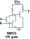
OR gates are basic logic gates, and are available in TTL and CMOS ICs logic families. The standard 4000 series CMOS IC is the 4071, which includes four independent two-input OR gates. The TTL device is the 7432. There are many offshoots of the original 7432 OR gate, all having the same pinout but different internal architecture, allowing them to operate in different voltage ranges and/or at higher speeds. In addition to the standard 2-input OR gate, 3- and 4-input OR gates are also available. In the CMOS series, these are:
- 4075: triple 3-input OR gate
- 4072: dual 4-input OR gate
Variations include:
- 74LS32: quad 2-input OR gate (low power Schottky version)
- 74HC32: quad 2-input OR gate (high speed CMOS version) - has lower current consumption/wider voltage range
- 74AC32: quad 2-input OR gate (advanced CMOS version) - similar to 74HC32, but with significantly faster switching speeds and stronger drive
- 74LVC32: low voltage CMOS version of the same.
Implementations
Summarize
Perspective
Analytical representation
is the analytical representation of OR gate:
OR gates with many inputs
OR gates with multiple inputs are designated with the same symbol, with more lines leading in.[8] While direct implementations with more than three inputs are possible in logic families like CMOS, these are inefficient. More efficient implementations use a cascade of NOR and NAND gates, as shown in the picture below.
- 12-input OR gate realized via a cascade of NOR and NAND gates.
Alternatives
If no specific OR gates are available, one can be made from NAND or NOR gates in the configuration shown in the image below. Any logic gate can be made from a combination of NAND or NOR gates.
Wired-OR

With active low open collector logic outputs, as used for control signals in many circuits, an OR function can be produced by wiring together several outputs. This arrangement is called a wired OR. This implementation of an OR function typically is also found in integrated circuits of N or P-type only transistor processes.
See also
Wikimedia Commons has media related to OR gates.
References
Wikiwand in your browser!
Seamless Wikipedia browsing. On steroids.
Every time you click a link to Wikipedia, Wiktionary or Wikiquote in your browser's search results, it will show the modern Wikiwand interface.
Wikiwand extension is a five stars, simple, with minimum permission required to keep your browsing private, safe and transparent.


