Loading AI tools
For Monopole antenna

A monopole antenna is a class of radio antenna consisting of a straight rod-shaped conductor, often mounted perpendicularly over some type of conductive surface, called a ground plane.[1][2][3] The current from the transmitter is applied, or for receiving antennas the output signal voltage to the receiver is taken, between the monopole and the ground plane. One side of the feedline to the transmitter or receiver is connected to the lower end of the monopole element, and the other side is connected to the ground plane, which may be the Earth. This contrasts with a dipole antenna which consists of two identical rod conductors, with the current from the transmitter applied between the two halves of the antenna. The monopole antenna is derived mathematically from the dipole. The vertical monopole is an omnidirectional antenna with a low gain of 2 - 5 dBi, and radiates most of its power in horizontal directions or low elevation angles. Common types of monopole antenna are the whip, rubber ducky, helical, umbrella, inverted-L and T-antenna, inverted-F, folded unipole antenna, mast radiator, and ground plane antennas.
The monopole is usually used as a resonant antenna; the rod functions as a resonator for radio waves, oscillating with standing waves of voltage and current along its length. The length of the antenna is determined by the wavelength of the radio waves it is used with. The most common form is the quarter-wave monopole, in which the antenna is approximately one quarter of the wavelength of the radio waves. It is said to be the most widely-used antenna in the world.[4] [5]. The half-wave monopole, one-half wavelength long, is also widely used, as are monopoles shorter than one-quarter wavelength, called electrically short monopoles. Monopoles five-eights (5/8 = 0.625) of a wavelength long are also common, because at this length a monopole radiates a maximum amount of its power in horizontal directions. A capacitively loaded or top-loaded monopole is a monopole antenna with horizontal conductors such as wires or screens insulated from ground attached to the top of the monopole element, to increase radiated power. Large top-loaded monopoles, the T and inverted L antennas and umbrella antenna are used as transmitting antennas at longer wavelengths, in the LF and VLF bands.
The monopole antenna was invented in 1895 by radio pioneer Guglielmo Marconi; for this reason it is also called the Marconi antenna although Alexander Popov independently invented it at about the same time.[6][7]
Types and uses
Due to their omnidirectional radiation pattern, vertical monopole antennas are commonly used in terrestrial radio communication systems in which the direction to the transmitter or receiver is unknown or constantly changing,[8] such as broadcasting, mobile two-way radios, and wireless devices like cellphones and Wi-fi networks,[9][5] because they radiate equal radio power in all horizontal directions but little power up into the sky where it would be wasted. The quarter-wave monopole is the smallest antenna that is resonant, making it an efficient radiator; it is said to be the most widely used antenna in the world.[5][4]
Lower frequency monopole antennas

200 foot mast radiator of AM radio station, USA

Amateur radio cage T antenna, used to communicate with Europe at frequency of 1.5 MHz, 1922

VLF flattop antenna at Grimeton Radio Station, Sweden

Trideco umbrella antenna of the VLF transmitter at Anthorn military radio station, UK, transmitting at 19.6 kHz

Amateur inverted-L antenna for shortwave reception, showing construction
Large monopoles are the main transmitting antennas used in the lower frequencies below 3 MHz, the MF, LF, and VLF bands, because the radio propagation mode used in these bands, ground waves, requires a vertically polarized antenna with good horizontal radiation characteristics.[10][11] At these frequencies, the Earth itself is used as the antenna's ground plane. The most common antenna is the mast radiator, a vertical mast mounted on the ground but insulated from it electrically.[10] ranging from about one-sixth to five-eighths wavelengths tall.[12] One side of the feedline from the transmitter is connected to the conductive metal mast which serves as the radiating element, and the other to an Earth ground connection at the base of the antenna. To reduce ground resistance this is usually a radial network of buried wires stretching outward from the base of the antenna. This design is used for AM radio broadcasting antennas in the MF and LF bands.[12] Another variant is the folded unipole antenna.[13] At lower frequencies in the LF and VLF band, construction limitations mean monopoles are electrically short, shorter than one-quarter wavelength. Simple monopoles this short are inefficient due to their very low radiation resistance, so to increase efficiency and radiated power, capacitively toploaded monopoles such as the inverted-L, T antenna and umbrella antenna are used.[14][10][15]
At higher frequencies in the shortwave bands variations such as the folded monopole, J-pole antenna[16], and normal mode helical[17] are used.
Higher frequency monopole antennas
_closeup.jpg)

Cell phone UHF whip antenna on car

3 fiberglas half-wave whip antennas

US Navy broadband conical monopole antenna


Dual band 2.4 and 5 Ghz monopole antenna on a home Wi-fi router
At higher frequencies in the VHF and UHF bands, the size of the ground plane needed is smaller, so artificial metal ground planes of screen or rods are used to allow the antenna to be mounted above the ground.[18][9] A common type for mounting on masts or stationary structures is the ground plane antenna, consisting of a quarter-wave whip antenna with a ground plane of 3 or 4 wires or rods a quarter-wavelength long radiating horizontally or diagonally from its base, connected to the ground side of the feedline.[19] Another variation is the discone antenna, which is notable for having a very broad bandwidth.[20] At frequencies above 30 MHz an automobile or aircraft body makes an adequate ground plane,[21][22] so whip antennas for two-way radios and cell phones are mounted on car bumpers or roofs,[9] and aircraft communication antennas frequently consist of a short conductor in an aerodynamic fairing projecting from the fuselage; this is called a blade antenna.[23][10]
The quarter-wave whip and rubber ducky antennas used with handheld radios such as walkie-talkies and portable FM radios in the VHF and UHF bands are also monopole antennas.[24][5] In these portable devices the antenna does not have an effective ground plane, the ground side of the transmitter or receiver is just connected to the chassis ground connection on its circuit board.[25] Since these "ground" conductors are no larger than the element itself the antenna usually functions more like an asymmetrical dipole than a monopole antenna.[26][27]
A monopole type widely used in wireless devices and cell phones operating at microwave frequencies is the inverted F antenna (IFA).[28][5] The monopole element is bent over in an L shape parallel to the ground area on the circuit board, to make it compact enough to be enclosed in the device case; the antenna may be fabricated of copper foil on the printed circuit board itself.[28] To improve the impedance match with the feed circuit the antenna is shunt fed, the feedline is connected to an intermediate point along the element, and the base of the element is grounded. Many variants of this antenna are used in handheld devices, such as multiband versions and meander antennas.[29]
History
Development of Marconi's monopole antenna from Hertz's dipole antenna
Hertz's dipole antenna transmitter, invented 1886
Marconi first tried enlarging the dipole antenna with 6×6 foot metal sheet "capacity areas" (r), 1895[30] Metal sheets and spark balls not shown to scale.
Illustration from Marconi's 1896 patent[30] showing his first monopole antennas, consisting of suspended metal plates (u,w) attached to one terminal of the transmitter (left) and receiver (right), with the other terminal grounded (E). Later he found that the plates were unnecessary and a suspended wire was adequate.
Marconi's first monopole transmitter
One of Marconi's early monopole antennas at his Poldhu, Cornwall transmitting station, 1900, consisting of a small metal plate suspended from a wooden arm with a long wire running down to the transmitter in the building.

Early vertical antennas. (A) Marconi found suspending the metal plate "capacity area" high above the ground increased range. (B) He found that a simple elevated wire worked just as well. (C-F) Researchers found that multiple parallel wires were a better way to increase capacitance. "Cage antennas" (E-F) distributed current more equally between wires, reducing resistance
The monopole antenna was invented in 1895 and patented in 1896[30] by radio entrepreneur Guglielmo Marconi during his first experiments in radio communication.[31][32] He began by using dipole antennas invented by Heinrich Hertz consisting of two identical horizontal wires ending in metal plates, and by his mentor Augusto Righi consisting of four metal spark balls, but was unable to transmit further than about a half mile. He found by experiment that if instead of the dipole, one side of the transmitter and receiver terminals was connected to a wire suspended overhead, and the other side was connected to a conductor buried in the Earth, he could transmit for longer distances.[33][note 1] For this reason the monopole is also called a Marconi antenna,[6][7] although Alexander Popov independently invented it at about the same time for his lightning detection receiver.[31][34]
 Marconi's transmitting antenna at Poldhu, UK, used 1901 in first transatlantic contact, a 160 foot fan-shaped 50-wire monopole.
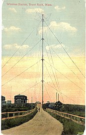 Fessenden's 1906 Brant Rock, MA transatlantic transmitter, an early mast radiator


In the next few years, using the monopole antenna Marconi steadily increased the range of his radiotelegraphy communication system to hundreds of kilometers, convincing the world that radio was a practical communication method. In 1901 he achieved transatlantic radio transmission using a monopole transmitting antenna consisting of 50 vertical wires suspended in a fan shape from 60 meter poles. [34]
Before Marconi, several inventors experimented with wireless communication between vertical aerials, although without creating a practical system.[35] In October 1866 Mahlon Loomis demonstrated communication between two grounded 183-meter (600-foot) wire aerials supported by kites on mountaintops 22 kilometres (14 miles) apart.[36] When one aerial wire was touched to a grounded contact, currents of atmospheric electricity in it apparently generated radio waves which induced currents in the other wire, detected by a sensitive galvanometer. Starting in 1882, Amos Dolbear also used grounded kite-supported vertical wire antennas during his development of a ground conduction telephone, but his system seems to have worked by electrostatic induction instead of radio waves, and by 1895 he had only achieved distances of 1/4 mile.[37] A suit claiming Marconi infringed Dolbear's 1882 and 1886 wireless patents was dismissed in 1901.[38] In 1885 Thomas Edison patented a system of ship communication between vertical towers on shore and vertical wires suspended from a ship's mast, but this also worked by electrostatic induction and was never tried.[39]
In the primitive spark transmitters used in Marconi's time, in addition to radiating the radio waves the antenna also served as the resonator which generated the oscillating currents which determine the frequency and thus the wavelength of the waves. Marconi's new antenna functioned as a quarter-wave monopole[40] which radiated with a wavelength of approximately four times its height.[41][42] This longer antenna greatly increased the wavelength, reducing the frequency of Marconi’s transmitter from the VHF and UHF bands generated by Hertz's antennas which could not transmit beyond the horizon, to the MF band.[43][34] Also, it emitted vertically polarized radio waves, instead of the horizontally polarized waves produced by the Hertz antenna.[44][45] Longer radio waves have less attenuation with distance. These longer vertically polarized waves could propagate as ground waves which can follow the curvature of the Earth, and could also reflect off the ionosphere (called the 'skip' or skywave mechanism), and thus travel beyond the visual horizon. This explains the increased range.[42][46]
Marconi, who was self-educated in physics, didn't understand any of this at the time;[42] he merely discovered an empirical relation between antenna height and transmission distance.[47][40][48] He credited Prof. Moisè Ascoli of Rome with first calculating in 1897 that the antenna radiated at a wavelength of four times its height.[42] An integral equation for the current in wire antennas was derived by Henry Pocklington in 1897,[42][49] who showed the current was approximately a sinusoidal standing wave.[50][51] In 1906 Prof. John Ambrose Fleming, engineer for the Marconi company, mathematically explained the radiation pattern and relation of the monopole to the dipole antenna using image theory.[52][53] A more useful version of the Pocklington equation, the Hallen equation, was derived by Erik Hallén beginning in 1938.[54][55] These integral equations are the starting point in modern analyses of monopoles, and are solved numerically in modern computer antenna simulation programs.[note 2]
Multiwire monopoles used during the radiotelegraphy era, 1900 - 1920s

Marconi 210 ft (64 meter) inverted cone monopole transmitting antenna, Poldhu, UK, built 1902

An inverted-L, "triatic" or "flattop" antenna, a monopole used in long distance radiotelegraphy transmitting stations at frequencies below 50 kHz, invented by Marconi in 1904

Umbrella antenna of radiotelegraph station near Newcastle, UK in 1910

T antenna of radio station WBZ, 833 kHz, Springfield, MA, built in 1921.
During the radiotelegraphy era, the first two decades of radio from 1900 until the 1920s, radio communication systems used long wavelengths below 1.5 MHz, in the MF, LF and VLF bands.[56] Monopoles were the main antennas used. At the longer wavelengths used for long distance communication the tallest antenna masts that could be practically constructed were shorter than the resonant length, one-quarter wavelength.[14] Monopole antennas this short are inefficient; due to their low radiation resistance of 5 to 20 ohms, a large fraction of the transmitter power was wasted in the ground system resistance.[57] At this time the main technique known for increasing radiated power was to add conductors to the top of the antenna, to increase the capacitance to ground and thus the antenna current.[58] Marconi and others developed huge multiwire capacitively top-loaded monopole antennas[59][53] which were more efficient at these frequencies,[60] such as the harp, inverted cone, inverted L, T antenna and umbrella antenna.[61][57] These were the main antennas during this period,[58] and the latter three are still the main transmitting antennas used at these low frequencies.[61] When radio broadcasting began in the MF band in the early 1920s, the typical transmitting antenna was the T-antenna.[62][57] This required two masts, an extensive land area, and currents in the masts distorted the radiation pattern.
Two papers published in 1924 by Stuart Ballantine led to the adoption of the single mast monopole radiator.[57] [63] One derived the radiation resistance of a vertical monopole antenna over a perfect ground plane.[64] He found that the radiation resistance increased to a maximum at a length of a half wavelength, so a mast around that length had an input impedance that was much higher than the ground resistance, reducing the fraction of transmitter power that was lost in the ground system, eliminating the need for capacitive toploads. In a second paper the same year he showed that the amount of power radiated horizontally in ground waves reached a maximum at a mast height of 5/8 wavelength (.625
The advent of handheld radios in the 1950s-60s, the transistor radio and walkie-talkie, made possible by the invention of the transistor in 1947, motivated the development of compact monopole antennas for them, like the retractable quarter-wave whip and the rubber ducky antenna.
Elementary description of operation
A monopole antenna, like the dipole antenna from which it is derived, is a resonant antenna; it not only emits and receives radio waves but acts as an electrical resonator.[68] When the radio frequency alternating current applied to its feedpoint is near one of its resonant frequencies, in addition to radiating the power as radio waves, energy is stored in the antenna as oscillating electric currents called standing waves. The advantage of this is that the stored energy is larger than the energy fed to the antenna each cycle by the transmitter (or in a receiving antenna the energy absorbed from the radio waves), so most of the current in the antenna is due to this stored energy. As a result the antenna current at resonance is larger than the current when the antenna is driven at other frequencies. The radio wave power radiated by an antenna is proportional to the square of the antenna current, so an antenna fed at a resonant frequency radiates much more power than the same antenna fed with the same voltage at some other frequency.[69] An antenna only absorbs all the input power from the feedline when it is in a condition of resonance.
The vertical conductor acts somewhat like a transmission line stub, open-circuited at the top. The oscillation modes are analogous to the mechanical oscillations of an elastic beam anchored at one end.[70] The current and voltage along the element are sinusoidal waves. The current in the antenna element bounces back and forth between the ends, and the two equal but opposite current waves interfere to form a standing wave.[71] [72] The standing wave has a current node at its top and either a node or an antinode at bottom. Due to these end conditions the antenna is resonant (has pure resistive input impedance) at a length of a quarter wavelength or multiples of it.[73]
In the common quarter wave monopole, the top end of the vertical rod and the ground plane act as capacitor plates which have opposite charges, storing energy in an electric field, while the middle of the rod acts as an inductor which stores energy in a magnetic field,[72] so the entire antenna acts like a series-resonant tuned circuit. If the top of the rod is negatively charged and the ground plane positively charged at the beginning of the cycle, the current begins to flow up the rod from the ground plane, creating a circular magnetic field around the rod. The negative charge at the top and positive charge on the ground plane decrease until they reach zero. However the current continues, because the inductance of the rod resists changes in current. The current begins to charge the top of the rod positive and the ground plane negative. From Faraday's law of induction the energy to create this separation of charge comes from the magnetic field, which decreases. Finally when the magnetic field reaches zero the current stops with the charges reversed, the top of the rod is charged positive and the ground plane negative. Then the current begins to flow in the opposite direction, down the rod, generating a magnetic field circling in the opposite direction, until the charges reverse again to their original polarity, with the top of the rod negative and the ground plane positive. This oscillation keeps repeating, with the energy stored alternately in the electric field and the magnetic field each half-cycle of the applied alternating current.
Most of these coupled oscillating electric and magnetic fields are near fields (also called reactive or induction fields) which store energy in the space around the antenna, but some of the fields leave the antenna and travel away as electromagnetic waves, radio waves, carrying energy with them. The radiated power is provided by incoming power from the feedline. Due to this power loss, an antenna acts as if it has a resistance, the radiation resistance, at its feedpoint.
As a result, a monopole acts electrically like a lossy tuned circuit; in general it has both electrical resistance and reactance at its feedpoint.[74] The input resistance has two components; the radiation resistance (normally the largest part) and the loss resistance due to ohmic losses in the antenna conductor and ground plane. At resonance the input impedance is just this pure resistance; at other frequencies it has reactance in addition to the resistance, and thus a higher impedance.
A transmitting antenna will absorb all the power applied to its feedpoint only if it is conjugate impedance matched to the feedline from the transmitter. This means the resistance of the antenna and line must be equal, and the reactance of antenna and line must be opposite. If it is not impedance matched, some of the transmitter power from the feedline will be reflected back down the line toward the transmitter, causing a high SWR, resulting in inefficiency and possibly overheating the transmitter or line, or causing arcing. Similarly, a receiving antenna will only transfer a maximum amount of radio power to the receiver if it is impedance matched to the line.
Ground plane
Most monopoles have a conducting surface under the vertical rod, a ground plane, connected to the ground side of the feedline.[2] The ground plane is an integral part of the antenna; it has two functions. First, it reflects the downward directed radio waves from the rod, increasing the power radiated above the ground. Second, it acts as a capacitor plate, receiving the displacement current (alternating electric field) from the rod, returning it to the ground side of the feedline.[75][76] Without it there will be induced currents on the outside of the shield conductor of the feedline, which will act as an antenna.
The current in the ground plane is radial, directed alternately toward and away from the ground terminal at the base of the antenna. Therefore far from the antenna the radio waves radiated by the currents in opposite sides of the plane have opposite phase and largely cancel. So the plane itself does not radiate; it acts as a mirror for the radio waves from the rod.
The electric field is vertical where it enters the ground plane, identical to the field of a vertical dipole antenna at its symmetry plane. If the ground plane is large enough, due to the waves reflected from it the antenna acts as if it has an image antenna identical to the monopole underneath the plane.[77] The antenna rod and its image together act like a dipole antenna of twice the length, so a monopole over an infinite, perfectly conducting plane has a radiation pattern identical to the top half of the pattern of a vertical dipole of twice the length.[2] [78][79] For the quarter wave monopole, the antenna acts like a half wave dipole. Because the antenna only radiates its power into half the space of a dipole antenna, its gain is twice (or in decibels, 3 dB greater than) the gain of an equivalent dipole.[77]
The actual gain and radiation pattern is dependent on the size and conductivity of the ground plane.[25] To function as a mirror the plane must extend least a half wavelength from the monopole element. Low frequency monopole transmitting antennas use the Earth itself as the ground plane. They require a good low resistance connection to the Earth for efficiency, since the soil has significant resistance which is in series with the antenna and consumes transmitter power.[80] These use a radial ground system consisting of many bare copper wires buried shallowly in the earth, radiating from a ground terminal at the base of the antenna, preferably to a distance of a quarter to a half wavelength.[81][76]
Because of the unbalanced impedance of the ground plane, monopole antennas are most easily fed from an unbalanced transmission line, usually coaxial cable.
Current distribution on antenna
Calculating the current distribution along a thin linear antenna, which determines the radiation pattern and electrical characteristics, requires solving Maxwell's equations for the coupled current, electric and magnetic fields at the surface of the element, driven by the electric field of the sinusoidal feed voltage from the transmitter applied to the antenna's feedpoint (or in a receiving antenna by the incoming fields of the radio wave). The Pocklington integral equation (Henry Pocklington, 1897[49]) or Hallen integral equation (Erik Hallén, 1938[54][55]) give the current on thin cylindrical antennas.[50][51] In general, accurate calculation of an antenna's electrical properties is mathematically difficult, and antenna simulation computer programs like NEC are usually used.
If the ground plane is a good conductor larger in radius than the height of the element (which will be assumed in this section), it approximates a perfect infinite ground plane, and the current and radiation can be calculated by replacing the monopole and plane with a vertical dipole antenna of twice the height. For smaller planes, for accurate results resonances in the ground plane and refraction around the edges must also be taken into account, so the current distribution in the plane must be calculated, making analysis more difficult.
The current in the monopole element is approximately a sinusoidal standing wave 


From the Pocklington equation, to a first approximation, the current on a thin antenna is given by the Helmholtz equation[83][50]

This is the same as the Telegrapher's equation for a lossless transmission line, explaining why linear antennas behave like transmission lines. Solving for the monopole element, and applying the boundary condition 


where
is the wavenumber in radians per meter
is the loop current, the current at the antinode of the standing wave. In a monopole of
or longer it is the maximum current on the antenna.
is the input current at the base of the element, for base-fed monopoles
is the length of the monopole element.
is the height on the element measured from the ground plane


The current is close to 90° out of phase with the feed voltage at the bottom. It lags the feed voltage in a transmitting antenna and leads the feed in a receiving antenna.
This approximation assumes the Q_factor of the antenna is much greater than one;[note 3] in other words the stored energy is much larger than the feed energy per cycle which is equal to the radiated energy. This is a good approximation for a thin antenna driven at resonance. It is numerically accurate for a diameter-to-wavelength ratio less than .05, but applies qualitatively even to thick monopoles.[86] For finite width monopoles the current does not quite go to zero at the nodes, and the 180 degree phase change there is not abrupt but occurs continuously over a short distance centered on the node.[84]
Since this approximation assumes the energy applied by the feedline, and the energy lost to radiation, are negligible, the voltage across the feedline and the radiation resistance are implicitly assumed to be zero. A second approximation takes these factors into account. The current is the sum of two terms: the original sinusoidal wave which is 90° out of phase with the feed voltage, and a second smaller wave in phase with the feed voltage which supplies the radiated power.[87][88] This decreases with height along the element to zero at the top

(The input resistance is due to the radiation from the antenna which is neglected in the first approximation to the current, which Schelkunoff calls the 'asymptotic' approximation.)
The factor 
Radiation resistance and reactance
Radiation resistance 


For fast calculation the following approximate formulas are convenient[89]
where

Resonant frequencies and lengths
A monopole antenna is resonant (has pure resistive input impedance, no reactance) at a series of frequencies, which depend on its length 
Series resonances
The condition for resonance in a monopole, analogous to a vibrating string, is that when the sinusoidal current wave travels a round trip from one end of the monopole element to the other and back, the reflected wave must arrive at its starting point in phase with the original wave, so the two waves reinforce.[91]
The wave travels along the element at a velocity close to the speed of light 


Therefore the phase change in radians of the wave from one end of the element to the other is 

- The current reflects from the top with a 180° (
radians) phase change:[91] At the top of the element, the total current must be zero because there is no place for it to go, making this point a current node (zero) of the standing wave. So the upward and downward traveling waves must have equal but opposite amplitude there,
, The upward current wave is said to "reflect" from the top end of the element with opposite phase.
- The current reflects from the ground plane with no phase change: The downward wave travels down the element, through the feedline to the transmitter and back, and at the bottom reflects from the ground plane to become the upward wave. The ground plane, which can be modeled as a large capacitor plate connected to the ground conductor of the feedline, acts as a current source or sink, its voltage is approximately zero regardless of the current into it. Therefore the element has a voltage node (zero) and a current antinode (maximum) there. Since the voltage waves must be equal and opposite at the ground plane,
, and there is a sign change due to the opposite directions of the currents, the upward and downward current waves are always equal in amplitude there, they are in phase


![{\displaystyle i_{\text{up}}(0,t)=-C{dv_{\text{up}}(0,t) \over dt}=-C{d[-v_{\text{down}}(0,t)] \over dt}=i_{\text{down}}(0,t)}](http://wikimedia.org/api/rest_v1/media/math/render/svg/6fda8f5ed38eb2c13ba308ea3bd11a4921025e23)
The sine wave repeats every 


Solving for 


(The resonant lengths are actually slightly shorter than this, see End effects section below.) For a given length 

The lowest resonant frequency, 
These are sometimes called the series resonant frequencies because the antenna acts similar electrically to a series resonant tuned circuit.[98][99] Because the feedpoint at the bottom of the antenna is a voltage node (minimum) and current antinode (maximum), at these frequencies the input impedance, equal to the ratio of voltage to current, is a minimum. For a
Parallel resonances
The monopole can also resonate at a second series of lengths, at which the bottom end of the element is a current node (minimum) instead of a current antinode (maximum). So the element has a node of the current standing wave at both top and bottom, it is equivalent to an end-fed vertical dipole antenna (many sources classify this antenna as a dipole instead of a monopole[73]). The resonant frequencies can be calculated by a derivation similar to that in the previous section, but it is easier to note that a standing wave has a node at intervals of one-half wavelength. Therefore the antenna is resonant at lengths at which it is a half-wavelength long or a multiple of it[95][93]


For a given length

These are sometimes called parallel resonances or antiresonances because the antenna acts similar to a parallel resonant (antiresonant) tuned circuit.[100][101] When fed at the bottom, due to the current node and voltage antinode there the antenna has a very high input resistance, which is difficult to calculate.[102] It would be infinite for an infinitely thin element, but for a typical finite thickness monopole element it is around 1000 - 4000 ohms depending on thickness.[103][104] It also has a very high rate of change of reactance with frequency about the resonance point, which gives the antenna a narrower bandwidth than at the series resonances.[105]
To reduce the impedance enough to match a transmission line, either an impedance matching circuit, shunt feed, or a very thick monopole element must be used. An advantage is that since it acts as a dipole the current in the ground system is low, so ground losses are minimized; for thin antennas a ground plane is not needed at all.
In practice monopoles are mainly used at the two lowest resonant frequencies; where the element is one quarter of the wavelength long (
End effects

 is the reduction factor above, the resonant length of a quarter wave monopole is
As the ratio of rod diameter to wavelength increases, the node of the standing wave moves further above the end of the element, so at a given frequency the antenna is resonant at a shorter length.
The lengths at which physical monopoles are resonant are a little shorter than the theoretical resonant lengths
This is due to the shape of the electric field (fringing field) at the top end of the element which spreads out in a fan. This adds capacitance and reduces the inductance at the end.[110] [109] Due to this ability to store more charge, near the top the standing wave current profile differs from a sine wave, decreasing faster with distance.[109] When approximated as a sine wave, this is equivalent to the node of the standing wave occurring not at the top of the antenna but some distance above it.[note 4] So the resonant length of the element is shorter than a multiple of one quarter of the free space wavelength 
Another common way of saying this is that the resonant frequencies depend on the electrical length of the element (length in wavelengths of the current in the conductor), not the physical length (length measured in wavelengths of the radio wave in free space).[111][112] The electrical length of a linear antenna is longer than its physical length, so the resonant frequencies are lower than would be calculated from its physical length.
A thin monopole exactly one-quarter free space wavelength long, .25
In addition, anything which adds capacitance to the antenna element, such as the presence of grounded objects or high permittivity dielectric materials like insulating coatings or supporting electrical insulators near the end of the element will further decrease the resonant length.[111][106]
These are collectively called "end effects".[106] As a rule of thumb, due to these effects the resonant length

In the rest of the article, when the resonant length of a monopole is mentioned, it is assumed to include this correction.
(The approximate standing wave is 

Radiation pattern

 ) through a half-wave (0.5) to a maximum at five-eights wavelength (.625)
Like a vertical dipole antenna, a monopole has an omnidirectional radiation pattern: it radiates equal power in all azimuthal directions perpendicular to the antenna axis.[2][117][118] The radiated power varies with elevation angle, with the radiation dropping off to zero at the zenith on the antenna axis. The radio waves are vertically polarized, with the electric field parallel to the element.
A monopole can be visualized (see diagram) as being formed by replacing the bottom half of a vertical dipole antenna (c) with a conducting plane (ground plane) at right-angles to the remaining half.[78][119][79] If the ground plane is large enough, the radio waves from the remaining upper half of the dipole (a) reflected from the ground plane will seem to come from an image antenna (b) forming the missing half of the dipole, which adds to the direct radiation to form a dipole radiation pattern. So the pattern of a monopole over a perfectly conducting, infinite ground plane is identical to the top half of a dipole pattern.
Up to a length of a half-wavelength (

Above a half-wavelength the pattern splits into a horizontal main lobe and a small second conical lobe at an angle of 60° elevation into the sky.[122][123] However the horizontal radiated power and gain keeps increasing and reaches a maximum at a length of five-eighths wavelength: 

Above 

The general effect of electrically small ground planes, as well as imperfectly conducting earth grounds, is to tilt the direction of maximum radiation up to higher elevation angles and reduce the gain.[2][125]. When mounted on the Earth, due to the finite resistance of the soil the portion of the ground wave propagating horizontally in contact with the ground is attenuated exponentially and vanishes at long distances, so in the (far field) radiation pattern the radiated power declines smoothly to zero at the horizon (zero elevation angle).[109][120]
With an asymmetrical ground plane, such as a whip antenna mounted on a car’s bumper,the pattern will no longer be omnidirectional, but will have stronger horizontal radiation on the side with the larger ground plane area.
Gain and input impedance
More information Length ...
...| Length wavelengths |
Gain dBi |
3dB Beamwidth degrees[129][note 5] |
Radiation resistance ohms |
|
|---|---|---|---|---|
| ≪0.25 | 4.76 | 45° |  |
electrically short |
| 0.25 | 5.19 | 39° | 36.5 | fundamental |
| 0.375 | 5.75 | 32° | 92.8 | |
| 0.5 | 6.82 | 24° | >600 | 2nd harmonic |
| 0.625 | 8.16 | 16° | 53.2 | maximum gain |
| 0.75 | [note 6] | 52.7 | 3rd harmonic |
Close

Because it radiates only into the space above the ground plane, or half the space of a dipole antenna, a monopole antenna over a perfectly conducting infinite ground plane will have a gain of twice (3 dB greater than) the gain of a similar dipole antenna, and a radiation resistance half that of a dipole.[130][131] Since a half-wave dipole has a gain of 2.19 dBi and a radiation resistance of 73.1 ohms, a quarter-wave (
The gain figures given in the table above are never approached in practice; they would only be achieved if the antenna was mounted over an infinite perfectly conducting ground plane. The ground plane is part of the antenna, and the gain is highly dependent on its size and conductivity. An artificial ground plane a wavelength or more in radius is equivalent to a infinite plane,[25] but for smaller planes, which are often used at high frequencies, the gain will be 2 to 5 dBi lower, because some of the horizontal radiated power will diffract around the plane edge into the lower half space.[120][130] Similarly over a resistive Earth ground the gain will be lower due to power absorbed in the Earth.
For electrically short monopoles below 
As the length is increased to a half-wavelength (
The gain continues to increase up to a maximum of about 3 dB over a quarter-wave monopole at a length of five-eighths wavelength (
Directivity equation
The power density 


where
radians, or
degrees, is the electrical length of the monopole element


For a quarter wavelength and shorter this is approximately a cotangent pattern

Impedance matching
A transmitting antenna will absorb all the power supplied by the transmitter feedline, and in a receiving antenna the receiver will absorb maximum power from the antenna, only if the antenna is impedance matched to the transmitter or receiver.[134] This means the impedance presented by the feedline must be the complex conjugate of the input impedance of the antenna; they must have equal resistance and opposite reactance at the operating frequency. For efficiency most transmitting monopoles are impedance matched to the feed circuit. For receiving antennas below 30 MHz matching is not very important since losses in the feed circuit can be compensated by amplification in the receiver.
If the monopole's length is resonant at the operating frequency, the antenna impedance is a pure resistance, so for matching it is only necessary to transform the characteristic resistance of the feedline, if needed, to match the antenna resistance. Monopoles, as unbalanced loads, are usually fed with coaxial cable. The impedance of standard 50 or 75 ohm coaxial cable is a poor match to the 36.5 ohm radiation resistance of a quarter-wave monopole. A small monopole's impedance can be raised to match 50 ohm coax by an impedance matching network, tilting the ground plane rods diagonally down, or adding a cylindrical sheet metal 'sleeve' around the bottom, this is called a sleeved monopole.[21]
In many circumstances it is not convenient or not possible to use an antenna of resonant length. If a transmitting monopole antenna is operated at a frequency different from its resonant frequencies, the antenna will have reactance and will reflect some of the input power back down the feedline toward the transmitter, causing a high VSWR on the line, wasting energy and possibly overheating the line or transmitter or causing arcing.[134]
In this case the antenna can be made resonant at the desired frequency by canceling the reactance of the antenna by adding an equal but opposite reactance, an inductor or capacitor, in series with the feedline at the base of the antenna.[134] The antenna and reactance together act as a tuned circuit resonant at the feed frequency, with an input impedance that is purely resistive.
- A monopole shorter than a quarter wavelength will have capacitive reactance, so it can be made series resonant by adding an inductor called a loading coil at its base. This is called electrically lengthening the antenna. This technique is widely used to match a transmitter to an electrically short antenna that is a more convenient length.
- A monopole between a quarter and a half-wavelength will have inductive reactance, so it can be made series resonant by adding a capacitor at its base. This is called electrically shortening the antenna.
Bandwidth
The bandwidth of a monopole antenna, the range of frequencies over which it is resonant and works efficiently, increases with the thickness of the element. The radiated power and standing wave ratio (VSWR) on the feedline as a function of frequency is given by a smooth resonance curve similar to a tuned circuit, which has a peak at its resonant frequency. Surrounding the resonant frequency is a defined band of frequencies called the bandwidth 
The antenna's bandwidth 


However the usable bandwidth of an antenna is more often specified by a maximum voltage standing wave ratio (VSWR) which determines the maximum allowable transmitter power reflected by the antenna back down the feedline. Typical values are 1.5 or 2.
The bandwidth of a monopole increases with the width (diameter) of the conductive element. As the length-to-diameter ratio of the rod decreases, the standing wave current in the antenna departs from a sine wave and the resonance curve broadens. Bandwidth of a "typical" monopole antenna is around 10% of the resonant frequency, but ranges from 2% for a thin wire element to 30% for a thick rod. Where a really broadband monopole is needed a cage monopole is sometimes used, consisting of a fat cylindrical element made of an open latticework of metal rods.
Types of feed
Because in a resonant antenna the energy fed to the antenna by the transmitter each cycle is small compared to the energy stored in the standing wave on the antenna, the feed current can be applied at different points on the antenna without altering the current standing wave pattern much; leaving the radiation pattern the same. The advantage of this is that at different points on the antenna the input impedance has different values, allowing the possibility of impedance matching the antenna to the feedline characteristic impedance without a matching network, by choosing the correct feedpoint.
- Series or base feed - This is the most common type, the type discussed above, in which the feedline is connected between the base of the monopole and the ground plane. For the
monopole, the impedance is very high, requiring a matching transformer or thick monopole.
- Shunt feed - One side of the feedline is connected to ground, and the other to a point along the antenna element, and the base of the element is grounded. The part of the element between the feedpoint and ground acts as a shorted stub. Since the impedance is zero at the base and increases continuously to a very high value, 800 - 4000 ohms at a height of
- Gamma match - a shunt feed with a capacitor in the feedline connecting to the element.
- Folded monopole - A monopole can also be fed at the top, by grounding the base of the element, mounting a parallel conductor next to it, attached at the top, and feeding this conductor at the bottom. Because of their proximity the two elements are coupled so the current and voltage are the same in each. The folded monopole has a radiation resistance of 4 times the base fed monopole.
Electrically short monopoles
A monopole shorter than the fundamental resonance length of a quarter-wavelength at its operating frequency is called electrically short. Even a very short rod a small fraction of a wavelength long can be impedance matched to a transmitter so it absorbs all the power from the feedline. Electrically short monopoles are widely used since they are more compact, and for long wavelengths construction limitations make it impractical to build an antenna mast a quarter wavelength high. However as the length is decreased the antenna eventually becomes inefficient due to its low radiation resistance.[14][137]
Below a quarter wavelength the radiation resistance of a monopole decreases with the square of the ratio of length to wavelength

The radiation resistance is only part of the feedpoint resistance at the antenna terminals. A monopole has other energy losses which appear as additional resistance at the antenna terminals; ohmic resistance of the metal antenna elements, dielectric losses in insulating materials, feedline losses, and particularly resistive losses in the Earth ground system, often the largest loss factor in low frequency monopoles. The total feedpoint resistance 


The power 


where
and


The power 


As the monopole is made shorter it's radiation resistance decreases and a greater proportion of the transmitter power is dissipated in the loss resistance. At a length of 0.06
Another disadvantage of electrically short monopoles is that the low resistance combined with the high capacitance and inductance of the monopole element gives the antenna a large Q factor, it has a narrow bandwidth, which reduces the data rate that can be transmitted or received.
Capacitively top-loaded monopoles

To increase the radiated power of an electrically short monopole, capacitance to ground can be added to the top by attaching horizontal metal conductors, insulated from ground, to the top of the element.[142][14] This is called a top loaded monopole. This results in increased current in the vertical monopole element, to charge and discharge the capacitance each cycle. Since the power radiated by a monopole is proportional to the square of the current in the radiating element, this increases the radiated power. The buried radial wire ground system under the antenna serves as the bottom plate of the 'capacitor'.
Mast radiators sometimes include a circular structure of radial rods at the top of the mast; this is called a 'top hat'. At lower frequencies in the LF and VLF bands larger top loads are used. The T antenna consists of a vertical wire driven at the bottom, rising to attach to the center of a horizontal top load wire insulated at both ends, supported by masts. Multiple parallel top load wires can be used to increase capacitance. The largest top loaded antenna is the umbrella antenna, consisting of a monopole mast radiator with many diagonal top load wires radiating symmetrically from the top, anchored to the ground through insulators. To tune out the high capacitive reactance and make the antenna resonant a large loading coil is required in series with the feedline at the base of the antenna.
At low frequencies, due to the high capacitance and low radiation resistance, the top loaded monopole has a very narrow bandwidth. This may limit the width of sidebands and thus the data rate that can be transmitted. High power transmitting antennas in the VLF band typically have
Effective height
The radiation resistance and radiated power output of any monopole antenna can be calculated from its effective height 


where 

and the total radiated power

The effective height multiplied by the electric field of the radio wave is equal to the open circuit output voltage of the antenna. The effective height is also equal to the height of the charge center if the antenna were electrostatically charged. The effective height may be difficult to calculate in geometrically complex antennas, but for simple shapes
- Hypothetical constant current in a vertical monopole of height

- Trapezoidal current distribution:

- Quarter wave monopole antenna:

Definition of variables
More information  ,
,  ...
...
, ...| Symbol | Unit | Definition |
|---|---|---|
| radian | Phase shift of antenna current during round trip along element |
| meter (m) | Free space wavelength of radio waves |
| [none] | Math constant ≈ 3.1416 |
| radian | Elevation angle above horizon |
| meters per second (ms−1) | Velocity of light |
| hertz (Hz) | Frequency of radio waves |
 | hertz (Hz) | Resonant frequencies of monopole |
 | [none] | Electrical length, length in wavelengths, of the monopole element |
| meter (m) | length of monopole element |
 | ampere (A) | Upward current wave on antenna element at elevation z and time t |
 | ampere (A) | Downward current wave on antenna element at elevation z and time t |
| ampere (A) | Standing wave current on antenna element at elevation z |
 | ampere (A) | RMS current into antenna terminals |
 | ampere (A) | Maximum RMS current in antenna element |
 | ampere (A) | RMS current at an arbitrary point in antenna element |
 | meter−1 | Angular wavenumber  |
 | watt (W) | Electric power delivered to antenna terminals |
 | watt (W) | Power radiated as radio waves by antenna |
 | watt (W) | Power consumed in loss resistances of antenna |
| [none] | Q_factor of antenna, the resonant frequency divided by bandwidth |
 | ohm (Ω) | Radiation resistance of antenna |
 | ohm (Ω) | Equivalent loss resistance of antenna at input terminals |
 | ohm (Ω) | Input resistance of antenna |
 | ohm (Ω) | Radiation resistance at point of maximum current in antenna |
 | ohm (Ω) | Radiation resistance at arbitrary point in antenna |
 | second (s) | Time |
| meter (m) | Height on monopole element above lower end |
Close
Notes
- Hong 2010, p. 2-9, 17-23 discusses the reason Marconi, a self-educated tinkerer, made this discovery, and not the many educated physicists and professors who were also experimenting with wireless. This is generally attributed to the influence on physics of James Clerk Maxwell's 1873 electromagnetic theory, that proved that both light and radio waves were the same phenomenon; electromagnetic waves. Maxwell's theory conditioned physicists to think of radio waves as "invisible light". Thus they assumed that radio waves traveled in straight lines like light and were limited by the horizon. Therefore they believed radio systems could transmit no further than existing optical blinker light or semaphore communication systems, and so were useless for long distance communication. Marconi, an experimentalist free from this bias, thought of radio more as a telegraph without wires, and therefore he tried the telegraphy technique of using the ground as one side of the circuit.
- The history of the mathematical modeling of thin antennas is given in Raines 2007, p. 5-6 and in more detail in King 1956, p. 4-8. The integral equations of Pocklington and Hallen gave series approximations for the current and fields but could only be solved for simple geometries. Prior to computers, the radiation pattern of antennas was calculated either by solving one of these equations, or if this was not possible, by simply assuming a sinusoidal current distribution similar to a transmission line, and calculating the fields from Maxwell's equations using radiation integrals. In 1968 Roger F. Harrington published his book on the method of moments, a finite difference numerical algorithm that could calculate the currents and radiation of an arbitrarily shaped antenna modeled by a network of wire segments. This became the basis of the first widely used antenna simulation computer programs like NEC, which was written in 1979. These programs made antenna currents and radiation patterns easy to calculate without complicated math, so as computers became more widespread since 1980 they have become the standard method of design and the older transmission line methods have become less widely known.
- The Q of real antennas is never large. It is impossible practically to make an antenna thin enough with a high enough conductivity to get a Q over 20. But theoretically as the antenna is made thinner the Q goes to infinity.Schelkunoff & Friis 1952, p. 259
- The effect of this on the antenna is similar to if the current wave traveled along the element at a phase velocity
that is lower than the speed of light
, as in a transmission line. Some sources describe it this way: Carr & Hippisley 2012, p. 105; Rudge & Milne 1982, p. 564. However the phase velocity is not constant along the element, as in a transmission line.
- This is the elevation angle above the horizon at which the radiated power drops to half maximum
- The direction of maximum radiation at this and higher harmonics is not horizontal but directed at an angle into the sky

Footnotes
- Poisel 2012, p. 223.
- Straw 2000, p. 2.17.
- Orfanidis 2016, p. 785.
- Balanis 2005, p. 195.
- US Army 1953, p. 108-109.
- Kissick 2001, p. 17-19.
- Gosling 1998, p. 97-101.
- Rudge & Milne 1982, p. 553.
- Johnson 1993, p. 25.2.
- Raines 2007, p. 1.
- Rudge & Milne 1982, p. 554-556.
- Johnson 1993, p. 24.8-24.11.
- Carr & Hippisley 2012, p. 430.
- Johnson 1993, p. 13.18-13.19.
- Carr & Hippisley 2012, p. 233.
- Kumar & Shukla 2015, p. 250.
- Johnson 1993, p. 27.14.
- Lewis 2013, p. 34.
- Johnson 1993, p. 26.20.
- MacNamara 2010, p. 145.
- Johnson 1993, p. 27.21.
- Seybold 2005, p. 48-49.
- Fujimoto 2008, p. 216, 220.
- Chen & Chia 2006, p. 135-138.
- British patent 189612039 Marconi, Guglielmo Improvements in transmitting electrical impulses and signals, and in apparatus therefore, Applied: 2 June 1896, full specification: 2 March 1897, granted: 2 July 1897. British patents allowed the full specification to be submitted after the application. Marconi's monopole antenna did not appear in his initial June 1896 application but in his March 1897 specification. Corresponding US patent 586193, Marconi, Guglielmo, Transmitting electrical signals, filed 7 December 1896, granted: 13 July 1897
- Visser 2006, p. 31.
- page 192-196
- page 192-196
- Stutzman & Thiele 2012, p. 8.
- page 193-194
- Sarkar, Mailloux & Oliner 2006, p. 251, 352.
- Sarkar, Mailloux & Oliner 2006, p. 254.
- "Suit against Marconi dismissed". New York Tribune. New York. 23 March 1901. p. 7. Retrieved 8 August 2023.
- Sarkar, Mailloux & Oliner 2006, p. 255.
- Stutzman & Thiele 2012, p. 7.
- Fleming 1906, p. 272.
- Visser 2006, p. 32.
- page 196-197
- Eccles, W. H. (22 November 1905). "Earthed and unearthed radiators in wireless telegraphy". Electricity. 29 (21). Electricity Newspaper Co.: 287. Retrieved 1 March 2023.
- page 196
- page 196
- Fleming 1906, p. 601.
- page 196
- Pocklington, Henry C. (October 25, 1897). "Electrical oscillations in wires". Proc. Cambridge Philosophical Society. 9. London, UK: Cambridge Philosophical Society: 324–332. Retrieved 21 July 2022.
- Raines 2007, p. 10.
- Orfanidis 2016, p. 1179.
- Fleming 1906, p. 345-348.
- Visser 2006, p. 36.
- Hallén, Erik (January 1938). "Theoretical Investigations into Transmitting and Receiving Qualities of Antennas". Nova Acta Regiae Societatis Scientiarum Upsaliensis. 1. Uppsala, Sweden: Kungliga Vetenskaps-Societete (Swedish Royal Society of Sciences): 44.
- Hallén, Erik (1956). "Exact treatment of antenna current wave reflection at the end of a tube-shaped cylindrical antenna" (PDF). IRE Transactions on Antennas and Propagation. 4 (3). Institute of Radio Engineers: 479–491. doi:10.1109/TAP.1956.1144401. ISSN 0096-1973. Retrieved 22 July 2022.
- Stutzman & Thiele 2012, p. 9.
- Laport 1952, p. 77.
- Jansky 1919, p. 173-174.
- Sarkar, Mailloux & Oliner 2006, p. 382-385.
- page 197
- Johnson 1993, p. 24.4.
- Griffith 2000, p. 366.
- Rudge & Milne 1982, p. 556.
- Ballantine, Stuart (December 1924). "On the Radiation Resistance of a Simple Vertical Antenna at Wave Lengths below the Fundamental". Proceedings of the Institute of Radio Engineers. 12 (6). Institute of Electrical and Electronic Engineers: 823–832. doi:10.1109/JRPROC.1924.220010. S2CID 51654399. Retrieved 18 April 2020.
- Ballantine, Stuart (December 1924). "On the Optimum Transmitting Wave Length for a Vertical Antenna over Perfect Earth". Proceedings of the Institute of Radio Engineers. 12 (6). Institute of Electrical and Electronic Engineers: 833–839. doi:10.1109/JRPROC.1924.220011. S2CID 51639724. Retrieved 15 April 2020.
- "Half Wave Mast Antenna: A 665 foot structure which constitutes a new departure" (PDF). Radio-Craft. 3 (5). Mount Morris, Illinois: Techni-Craft Publishing Corp.: 269 November 1931. Retrieved August 31, 2014.
- Laport 1952, p. 79.
- US Army 1953, p. 66.
- War Department 1943, p. 141.
- US Army 1953, p. 54-57.
- Sielaff 1963, p. 141.
- Gosling 1998, p. 41-43.
- Carr & Hippisley 2012, p. 242.
- Griffith 2000, p. 351.
- Griffith 2000, p. 343-345.
- Balanis 2005, p. 191-193.
- Stutzman & Thiele 2012, p. 78.
- Carr & Hippisley 2012, p. 237.
- Johnson 1993, p. 24.25, 25.11.
- Raines 2007, p. 11, 13-14.
- Orfanidis 2016, p. 775.
- Williams 2007, p. 715.
- Kumar & Shukla 2015, p. 223.
- Balanis 2005, p. 442.
- Schelkunoff & Friis 1952, p. 252.
- Balanis 2005, p. 181 eq.4-81.
- Balanis 2005, p. 193.
- Schelkunoff & Friis 1952, p. 243.
- this is stated for a dipole in Gosling 1998, p. 38-39. A monopole acts like a dipole with the other half of the antenna provided by an image in the ground, so this also applies to the monopole.
- equivalent formula for dipole derived in Gosling 1998, p. 41
- equivalent formula for a dipole in Balanis 2005, p. 510
- Schelkunoff & Friis 1952, p. 435.
- Carr & Hippisley 2012, p. 106.
- stated for dipole in Gosling 1998, p. 41-42
- stated for dipole in Balanis 2005, p. 195
- stated for a dipole in Schelkunoff & Friis 1952, p. 261
- stated for a dipole in Balanis 2005, p. 195
- Raines 2007, p. 6.
- Johnson 1993, p. 4.7, fig.4-3.
- stated for a dipole in Balanis 2005, p. 195
- Carr & Hippisley 2012, p. 105.
- Lewis 2013, p. 46.
- Carr & Hippisley 2012, p. 104-106.
- Rudge & Milne 1982, p. 564.
- Schelkunoff & Friis 1952, p. 245.
- Carr & Hippisley 2012, p. 104-105.
- Wallace & Andreasson 2015, p. 77.
- Balanis 2005, p. 184.
- in units of feet Carr & Hippisley 2012, p. 106,eq 3.31
- Schelkunoff & Friis 1952, p. 246, 420.
- Straw 2000, p. 2.18.
- Johnson 1993, p. 26.15.
- Orfanidis 2016, p. 784-785.
- Carr & Hippisley 2012, p. 236.
- Rudge & Milne 1982, p. 555-556.
- Johnson 1993, p. 25.3.
- Balanis 2005, p. 175.
- Schmitt 2002, p. 244.
- Weiner 2003, p. vi.
- Orfanidis 2016, p. 782.
- Rudge & Milne 1982, p. 555.
- Ellingson 2016, p. 36.
- Balanis 2005, p. 173.
- Weiner 2003, p. 3.
- Stutzman & Thiele 2012, p. 75-80.
- Griffith 2000, p. 336.
- Johnson 1993, p. 25.7.
- Gosling 1998, p. 43-45.
- Straw 2000, p. 2.5.
- Gosling 1998, p. 43.
- Gosling 1998, p. 46.
- Gosling 1998, p. 42-43.
- Straw 2000, p. 2.2.
- Carr & Hippisley 2012, p. 145-147.
References
- Aitken, Hugh G. J (1976). Syntony and spark : the origins of radio. John Wiley and Sons. ISBN 0471018163.
- ARRL (1949). The A.R.R.L. Antenna Book, 5th Ed. American Radio Relay League, Rumford Press, Concord, NH, USA.
- Balanis, Constantine (2005). Antenna Theory: Analysis and Design, 3rd Ed. John Wiley and Sons. ISBN 9781118585733.
- Bevelacqua, Peter J. (2016). "The Monopole Antenna". Antenna Types. Antenna-Theory.com website. Retrieved 20 August 2020.
- Carr, Joseph; Hippisley, George (2012). Practical Antenna Handbook, 5th Ed (PDF). McGraw-Hill. ISBN 9780071639590.
- Chen, Zhi Ning; Chia, Michael Yan Wah (2006). Broadband Planar Antennas: Design and Applications. John Wiley and Sons. ISBN 9780470871751.
- Das, Sisir K. (2016). Antenna and Wave Propagation. Tata McGraw-Hill Education. ISBN 978-1259006326.
- Ellingson, Steven W. (2016). Radio Systems Engineering. Cambridge University Press. ISBN 9781316785164.
- Fleming, John Ambrose (1906). The Principles of Electric Wave Telegraphy. London: Longmans Green and Co.
- Fujimoto, Kyohei (2008). Mobile Antenna Systems Handbook. Artech House. ISBN 9781596931275.
- Griffith, Benjamin Whitfield (2000). Radio-electronic Transmission Fundamentals. SciTech Publishing. ISBN 9781884932137.
- Gosling, William (1998). Radio Antennas and Propagation (PDF). Newnes. ISBN 0750637412.
- Hong, Sungook (2010). Wireless: From Marconi's Black-Box to the Audion. MIT Press. ISBN 9780262514194.
- Jansky, Cyril Methodius (1919). Principles of Radiotelegraphy. McGraw-Hill Book Co.
- Johnson, Richard C., Ed. (1993). Antenna Engineering Handbook, 3rd Ed (PDF). McGraw-Hill. ISBN 007032381X.
{{cite book}}: CS1 maint: multiple names: authors list (link) - Kissick, W. A. (April 2001). NIJ Guide 202-00: Antenna System Guide. by US National Institute of Science and Technology (NIST) for National Institute of Justice, US Dept. of Justice.
- Kumar, Sanjay; Shukla, Saurab (2015). Wave Propagation and Antenna Engineering. PHI Learning. ISBN 9788120351042.
- Laport, Edmund A. (1952). Radio Antenna Engineering. McGraw-Hill Book Co.
- Lewis, Geoff (2013). Newnes Communications Technology Handbook. Elsevier. ISBN 9781483101026.
- MacNamara, Thereza (2010). Introduction to Antenna Placement and Installation. USA: John Wiley and Sons. ISBN 978-0-470-01981-8.
- Orfanidis, Sophocles J. (2016). Electromagnetic Waves and Antennas. Rutgers Univ. website.
- Poisel, Richard (2012). Antenna Systems and Electronic Warfare Applications. Artech House. ISBN 9781608074846.
- Raines, Jeremy Keith (2007). Folded Unipole Antennas: Theory and Applications. McGraw-Hill. ISBN 978-0071510202.
- Rudge, Alan W.; Milne, K. (1982). The Handbook of Antenna Design, Vol. 2. IET. ISBN 9780906048870.
- Sarkar, T. K.; Mailloux, Robert; Oliner, Arthur A. (2006). History of Wireless. John Wiley and Sons. ISBN 978-0471783015.
- Schelkunoff, Sergei A.; Friis, Harold T. (1952). Antennas: Theory and Practice. John Wiley and Sons.
- Schmitt, Ron (2002). Electromagnetics Explained: A Handbook for Wireless RF, EMC, and High-Speed Electronics. Newnes. ISBN 9780750674034.
- Schweber, Bill (2017). "Understanding Antenna Specifications and Operation, Part 2". Article library. Digi-key Electronics website. Retrieved 28 June 2021.
- Seybold, John S. (2005). Introduction to RF Propagation. John Wiley and Sons. ISBN 9780471743682.
- Sielaff, Gerald W. (1963). Study Guide for Fundamentals of Radio. US Armed Forces Institute.
- Straw, R. Dean, Ed. (2000). The ARRL Antenna Book, 19th Ed. Newington, CT, USA: American Radio Relay League. ISBN 9780872598041.
{{cite book}}: CS1 maint: multiple names: authors list (link) - Stutzman, Warren L.; Thiele, Gary A. (2012). Antenna Theory and Design. John Wiley and Sons. ISBN 978-0470576649.
- US Army (1953). Training Manual TM11-666: Antennas and Radio Propagation. Department of the Army.
- Visser, Hubregt J. (2006). Array and Phased Array Antenna Basics. John Wiley and Sons. ISBN 0470871180.
- Wallace, Richard; Andreasson, Krister (2015). Introduction to RF and Microwave Passive Components. Artech House. ISBN 9781630810092.
- War Department (1943). Technical Manual TM 11-314: Antennas and Antenna Systems (PDF). US Dept. of Defense.
- Williams, Edmund, Ed. (2007). National Association of Broadcasters Engineering Handbook, 10th Ed. Taylor and Francis. ISBN 9780240807515.
{{cite book}}: CS1 maint: multiple names: authors list (link) - Wong, K. Daniel (2011). Fundamentals of Wireless Communication Engineering Technologies. John Wiley and Sons. ISBN 978-1118121092.
Further reading
- Weiner, Melvin M. (2003). Monopole antennas. USA: CRC Press. ISBN 0-8247-4844-1. In depth analysis, covering the equations and computational electromagnetics models used to analyze real-world monopoles, and focusing on the effects of imperfect ground planes
- King, Ronold W. P. (1956). The Theory of Linear Antennas. Harvard University Press. The most comprehensive reference manual before the advent of computer methods
Damping and bandwidth
- (unfinished)
Unlike modern transmitters which generate a continuous wave oscillating signal, spark-gap transmitters generate a series of damped waves, each consisting of an oscillating sine wave that declines exponentially to zero. The degree of damping, the number of cycles before the wave decays to zero, has an inverse relationship with the bandwidth, the frequency range over which the signal is spread.[1] The damping is determined by Q_factor of the transmitting circuit; the ratio of shunt conductance in the transmitter circuit to the inductance and capacitance.
- Very damped waves, where the wave decays to zero within a few cycles, have very wide bandwidth. Their energy is spread over a wide range of frequencies on either side of the center frequency, so it may overlap the frequencies of other transmitters, interfering with their signals. The early non-syntonic spark transmitters were characterized by high damping.
- Lightly damped "ringing" waves, which decline gradually over many cycles, have a narrower bandwidth and create a "purer" signal, with most of its energy concentrated in a narrow band of frequencies around a single frequency. Later syntonic spark transmitters had lighter damping.
- Continuous waves, consisting of an undamped sine wave, have all their energy concentrated at one frequency. Spark gap transmitters could not produce continuous waves, but the vacuum tube transmitters that replaced them could.
The degree of damping is determined by the amount of resistance in the resonant circuit, compared to the size of the capacitor. The resistance mostly consisted of the radiation resistance of the antenna, plus the dissipation in the spark. In inductively-coupled transmitters it also depended on the degree of coupling of the two coils. Much of the development of later transmitters was directed toward reducing the damping, trying to approach closer to the ideal "pure" continuous wave.
During the wireless era the damping was measured by the "decrement", the fractional decline of the amplitude during one cycle of the wave.[1] The decrement was defined as

(Stanley) For an LC circuit (Morecroft, p. 62), it is

Today the same thing is measured by a parameter called the Q. The relationship between decrement and Q factor is

(Terman p. 139)
Power output
The energy in each damped wave is limited to the energy stored in the capacitor, or in transmitters without a capacitor, in the antenna. The energy in joules is

where C is the capacitance of the capacitor in farads and V is the peak voltage on the capacitor when the spark gap fires. However only some of this power is radiated as radio waves. Some is dissipated as heat in the transmitter; mostly in the spark, but also in ohmic heating and dielectric losses in the circuit. If η is the efficiency of the transmitter, the fraction of input power radiated as radio waves, the peak output power of the transmitter is

The power input is mainly dissipated in two resistances; the radiation resistance of the antenna and the resistance of the spark gap. In a transmitter with a spark rate of fS sparks per second the average power output in watts is

It can be seen that the power output increases with the capacitance and the peak voltage on the capacitor before the spark gap fires. However, this is only the average power output; the communication distance depends more on the "peak" power in an individual damped wave. This also doesn't apply to the quenched gap transmitter, since the spark is extinguished for part of the radiating cycle
References
- "It is well known that the effect of regeneration... is equivalent to introducing a negative resistance reaction in the circuit." Armstrong (1922) "Some recent developments of regenerative circuits", p.244
- "...if the loop gain [of a feedback circuit] is sufficiently negative (i.e., the feedback is sufficiently positive) a negative resistance is achieved." Rezavi (2001) Design of Analog CMOS Integrated Circuits, p.506
- "One of the simplest ways to produce a negative resistance is to interconnect the input and output terminals of a one-way amplifier. This gives a regenerative arrangement because part of the output energy of the amplifier is fed back into the input." Crisson (1931) "Negative resistance and the Twin-21 type repeater", p.486
- "Negative resistance by means of feedback" in Pippard (2007) The Physics of Vibration, p.314-322
- "Many circuit topologies are capable of producing absolute negative resistance... The simplest type requires an amplifier with voltage gain greater than unity. [...] The input resistance is negative for values of Av > 1" Aluf (2012) Optoisolation Circuits, p.11
- "As is well recognised, [regeneration] consists of supplying energy by some process akin to feedback... thereby having the same effect as would the introduction of 'negative resistance'." Warner (1922) Superregeneration, p.25
- "Regeneration introduces a negative resistance into a circuit, such that its net positive resistance is reduced." Kitchin (1998) "High performance regenerative receiver design", p.25
In electrical engineering, inductance is a property of an electrical conductor by which a changing electric current through the conductor induces a voltage either in the conductor itself, called self-inductance, or in another nearby conductor, called mutual inductance. Inductance most commonly means self-inductance, which is a property of a conductor which causes it to oppose changes in current through it. A current through a conductor creates a magnetic field around the conductor. A changing current creates a changing magnetic field, causing the magnetic flux, the total magnetic field passing through the circuit, to change. From Faraday's law of induction, any change in the magnetic flux passing through a circuit induces a voltage (electromotive force) in the circuit; this is called by electromagnetic induction. Inductance is defined as the ratio 


From Lenz's law, this self-induced voltage, or "back EMF", in a conductor will be in a direction so as to oppose the change in current which created it, so inductance causes a conductor to oppose changes in current through it. The inductance of a circuit depends on the geometric shape of the conductors, and the magnetic permeability of nearby materials. An inductor is an electrical component which adds inductance to a circuit. It is usually made of a conductor in a helix or spiral shape.
The term inductance was coined by Oliver Heaviside in 1886.[1] It is customary to use the symbol
Mutual inductance is a property of two nearby electrical circuits by which a changing current in one circuit induces a voltage in the other circuit, by electromagnetic induction. If two circuits are close enough together, the magnetic field created by a current in one circuit will pass through the other circuit. Thus a changing current in one circuit will cause a changing magnetic flux through the other circuit, inducing an electromotive force in the other circuit due to Faraday's law. The mutual inductance 


Like inductance, mutual inductance is measured in henrys. Two circuits which are close enough together to have appreciable mutual inductance are said to be inductively coupled. A common electrical component with operates by mutual inductance is the transformer.
References
- Heaviside, Oliver (1894). Electrical Papers. Macmillan and Company. p. 271.
- Glenn Elert. "The Physics Hypertextbook: Inductance". Retrieved 2016-07-30.
- Michael W. Davidson (1995–2008). "Molecular Expressions: Electricity and Magnetism Introduction: Inductance".
Wikiwand in your browser!
Seamless Wikipedia browsing. On steroids.
Every time you click a link to Wikipedia, Wiktionary or Wikiquote in your browser's search results, it will show the modern Wikiwand interface.
Wikiwand extension is a five stars, simple, with minimum permission required to keep your browsing private, safe and transparent.